Posts

Week 11 - Programming TCP Sockets in Node.js

Programming TCP Sockets in Node.js Eager to know how sockets are programmed in Node? There are three variants of sockets in Node - i. TCP, ii. UDP, iii. UNIX domain. In this particular post, I will show you the basics of TCP socket programming in Node.js. There are two categories of TCP socket programs you can write - i. server, ii. client. A TCP server listens for connections to it from clients and send data to the client. A TCP client connects to a TCP server exchange data with it. The communication between client and server happens via sockets. Programming TCP sockets in Node requires the  net  module, which is an asynchronous wrapper for network programming. The  net  module is capable of many things, but for today we'll just focus on creating a TCP server and a client. Writing a TCP Server Here is an example of a very simple TCP server written in Node. Read the comments thoroughly, it explains how the code works. var net = require ( 'net' ); var HOS

Week 10 - Programming UDP Sockets in Node.js

For all things UDP in Node.js, you will need to use the  dgram  library, so read it up well and good. UDP Server Here is a simple example of a UDP server. var PORT = 33333 ; var HOST = '127.0.0.1' ; var dgram = require ( 'dgram' ); var server = dgram . createSocket ( 'udp4' ); server . on ( 'listening' , function () {      var address = server . address ();     console . log ( 'UDP Server listening on ' + address . address + ":" + address . port ); }); server . on ( 'message' , function ( message , remote ) {     console . log ( remote . address + ':' + remote . port + ' - ' + message ); }); server . bind ( PORT , HOST ); Things to Note HOST is optional in  server.bind() . If omitted, it will be listening on  0.0.0.0 , which might be what you want in some cases. The  message  event is fired, when a UDP packet arrives destined for this server. The  listeni

Week 8 -Implementation of NAT in Cisco Packet Tracer

Image
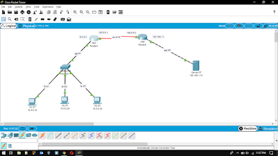
IMPLEMENTATION OF NAT IN CISCO PACKET TRACER Network address translation  ( NAT )  is a method of remapping one IP  address space  into another by modifying  network address  information in the  IP header  of packets while they are in transit across a traffic  routing device .  The main use of NAT is to limit the number of public IP addresses an organization or company must use, for both economy and security purposes. NAT inside and outside addresses : Inside refers to the addresses which must be translated. Outside refers to the addresses which are not in control of an organization. These are the network Addresses in which the translation of the addresses will be done. ·      Inside local address –  An IP address that is assigned to a host on the Inside (local) network. The address is probably not a IP address assigned by the service provider i.e., these are private IP address. This is the inside host seen from the inside network. ·         Inside global addre

Week 6 Implementation of DHCP in CISCO Packet Tracer

Image
The DHCP (dynamic host configuration protocol) is a standardized network protocol which is used in internet protocol (IP) networks. DHCP is used to assign IP automatically to the system with the help of a machine called DHCP server. A DHCP server enables computers to request IP addresses and networking parameters automatically. In the absence of a DHCP server, each computer on the network needs to statically (manually)  assigned to an IP address. Static IP addresses are usually assigned to routers, management interfaces on switches, servers and other devices in the network which do not change location either physically or logically. Static IP addresses are also used to access and manage these devices remotely. On the other hand, user devices such as computers, smartphones, IP phones and others are likely to change their locations either physically or logically. This means that assigning them static IP addresses would be an unviable solution. DHCP is a protocol that was i

Week 5: OSPF PROTOCOL CONFIGURATION IN CISCO PACKET TRACER

Image
OSPF is an Interior Gateway Protocol (IGP). OSPF was designed expressly for IP networks and it supports IP subnetting and tagging of externally derived routing information. OSPF also allows packet authentication and uses IP multicast when sending and receiving packets. The OSPF protocol is a link-state routing protocol, which means that the routers exchange topology information with their nearest neighbors. The topology information is flooded throughout the Autonomous System(AS). This picture is then used to calculate end-to-end paths through the AS, normally using  Dijkstra's algorithm. OSPF protocol network topology Configuration of OSPF using CLI in Cisco Packet Tracer: The steps to set up the RIP is same to some point as setting a router network link explained in previous blog. The further steps to follow are given below: Type  no ip route network_ip network_subnet gateway_router_address. (e.g.): no ip route 192.168.100.0 255.255.255.0 10.10.10.20 Then type